Controlling home appliances using SMS.
You must have interfaced so many modules with Arduino for your projects but ever have thought of designing your own custom module?
Here I will help you to design your own GSM-Sim800 and relay-based module to control your home appliances. I have used Atmel Atmega328 Microcontroller which is being used in Arduino UNO.
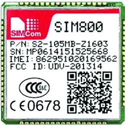
GSM SIM800

SIM800 is a complete Quad-band GSM/GPRS solution in a SMT type which can be embedded in any applications.
SIM800 support Quad-band 850/900/1800/1900MHz, it can transmit Voice, SMS and data information with low power consumption. With tiny size of 24x24x3mm, Featuring Bluetooth and Embedded AT.
General Features
- Quad-band 850/900/1800/1900MHz
- GPRS multi-slot class 12/10
- GPRS mobile station class B
- Bluetooth: compliant with 3.0+EDR
- Control via AT commands
- Supply voltage range 3.4 ~ 4.4V
What is Relay?
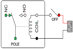
A Relay is an electromechanical switch to control (open and close) any circuit. It is mainly used to control any circuit automatically using small Dc voltage to drive high voltage devices.
Example: If you want to control your coffee maker with a simple Microcontroller, you can simply connect a relay and give digital commands.
 A normal SPDT DC relay have 5 pins, COM NC NO and a coil. Normally when no Voltage is applied on the relay coil NC (normally connected) pin and COM (Common) are in contact, when a DC voltage is applied according to desired rating of relay on its coil a movable armature consist of spring support moves and NO (normally Open) pin are now in contact with COM. You can connect your load between COM pin and NO pin.
For more details, please refer this blog on relays.
Bootloader and flashing to Atmega328 using Arduino
We are using atmega328 controller so we need to program it using Arduino as our board does not have USB uploading option. First thing is to upload bootloader on the chip then we can program the chip.

To burn the bootloader, follow these steps:
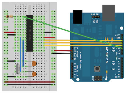
- Upload the ArduinoISP sketch onto your Arduino board. (You’ll need to select the board and serial port from the Tools menu that correspond to your board in Arduino IDE.)
- Wire up the Arduino board and microcontroller as shown in the diagram above.
- Select “Arduino Duemilanove or Nano w/ ATmega328” from the Tools > Board menu. (Or “ATmega328 on a breadboard (8 MHz internal clock)” if using the minimal configuration described below.)
- Select “Arduino as ISP” from Tools > Programmer
- Run Tools > Burn Bootloader
- You should only need to burn the bootloader once. After you’ve done so, you can remove the jumper wires connected to pins 10, 11, 12, and 13 of the Arduino board.
Uploading Using an Arduino Board
Once you have uploaded the Arduino bootloader on it, you can upload the program by simply replacing the current controller of Arduino UNO with this new controller or you can use USB-to-Serial converter (FTDI Chip) on an Arduino board to program by simply connecting its RX and TX lines.
Please refer this blog for more detail information about bootloading.
Wiring to Atmega328
We will be using Software serial for interfacing the Sim800 Gsm module with Atmega328.
- Rx of module is connected with D2 pin
- Tx of module is connected with D3 pin
- Reset of module is connected with D4 pin
- Relay Status led is connected with D6 pin
- Relay is connected with D7 pin
For more details, please refer the schematics. Download Eagle Files!
Working!
Once you have designed and assembled your module you are ready to test it, insert your SIM card to GSM module and lock it and now power the module. Connect the Antenna and now wait for some time (say 1 minute) and see the blinking rate of ‘status LED’ or ‘network LED’. GSM module will take some time to establish connection with mobile networks. Once the connection is established successfully, the status/network LED will blink continuously every 3 seconds. You may try making a call to the mobile number of the sim card inside GSM module. If you hear a ring back, the GSM module has been successfully established the network connection.
Now, your GSM module is working perfectly you are ready to code the microcontroller, insert the controller in arduino UNO and upload the code( Make sure you already had burned the bootloader). Take out the controller from UNO and place it inside your module and power it, once it establishes the network you will receive a confirmation message on your mobile number.
We are using Atmega328P EEPROM which is 1024 bytes for logging the previous command received by the GSM module. You can now send “ON” message using your mobile phone to turn the Relay ON and send “OFF” to turn it OFF. After every successful command you will receive a feedback message from the module.
Code!
#include <EEPROM.h>
#include <SoftwareSerial.h>
SoftwareSerial mySerialObj = SoftwareSerial(2,3);
SoftwareSerial *mySerial = &mySerialObj;

int address = 0;                // EEPROM address to store flag
byte val;                       // 1 means ON , 0 means OFF

#define RELAY_PIN 7
#define RELAY_STAT_PIN 6        // Relay Status Led
const String PhoneNo = "Your_Mobile Number";
const String Device_Name = "Basement Light";
Download the code.